TRAK Products
TRAK Machine Tools offers a comprehensive range of innovative machine tool solutions designed to enhance productivity and precision in machining operations. In addition to our renowned ProtoTRAK® CNCs with user-friendly conversational programming, we provide production machines equipped with the advanced SINUMERIK ONE® CNC for superior performance and efficiency.
Our lineup includes high-performance milling machines, lathes, and bed mills, delivering versatility and reliability for machinists, job shops, and manufacturing facilities. Whether you're upgrading your workshop or expanding production capabilities, TRAK Machine Tools provides precision-engineered solutions backed by industry-leading expertise and support.
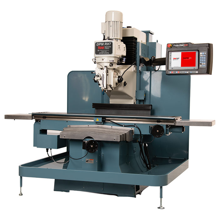
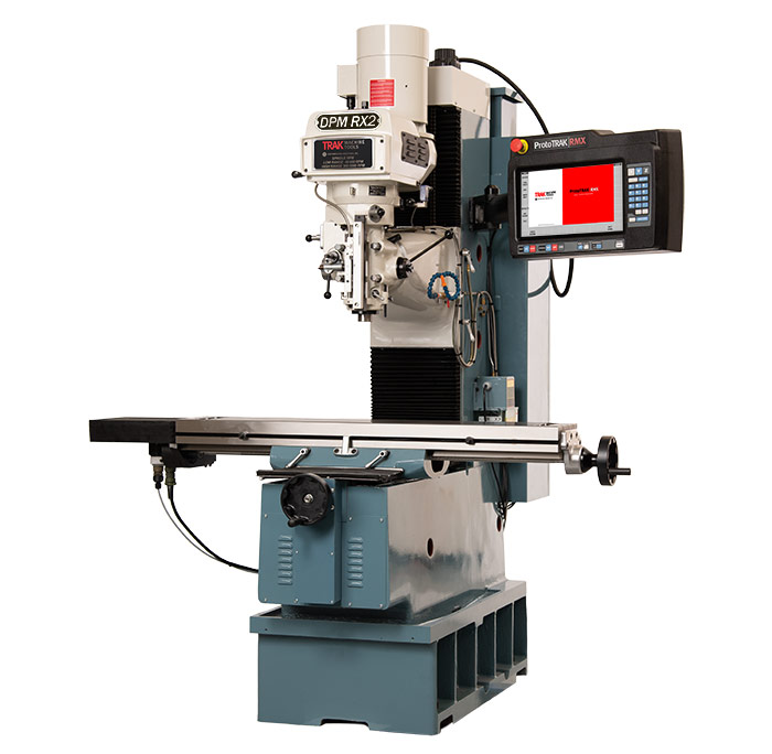
DPMRX Series Bed Mills
The TRAK DPMRX Series Bed Mills feature the ProtoTRAK RMX CNC for easy operation and precision machining. Built for versatility, they handle both manual and CNC work with ease.
-
Table Size:
76″ x 14″
-
Travels:
60″ x 23″ x 24.25″
-
Spindle Motor:
7.5 HP Continuous
-
Spindle Taper:
40 Taper
-
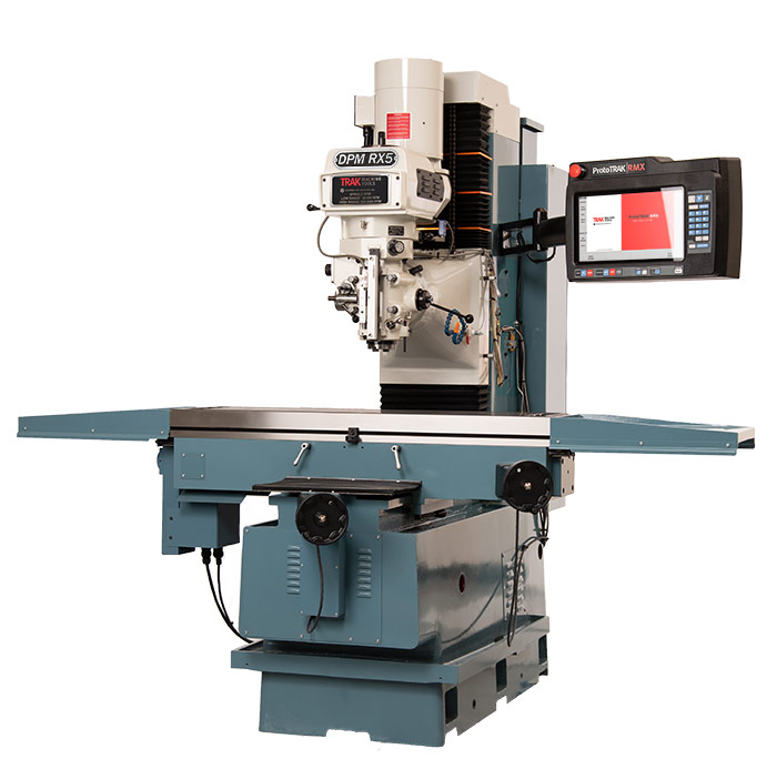
Table Size:
50″ x 12″
-
Travels:
40″ x 20″ x 25.81″
-
Spindle Motor:
5 HP Continuous
-
Spindle Taper:
40 Taper
-
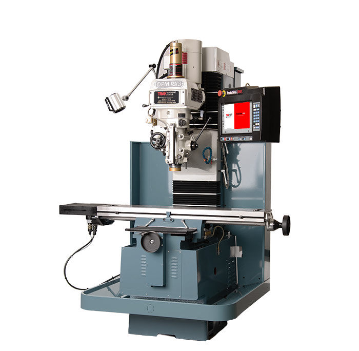
Table Size:
50″ x 10″
-
Travels:
31.5″ x 17″ x 25.81″
-
Spindle Motor:
5 HP Continuous
-
Spindle Taper:
40 Taper
-
Table Size:
49″ x 9″
-
Travels:
31.75″ x 16″ x 23.25″
-
Spindle Motor:
3 HP Continuous
-
Spindle Taper:
R8
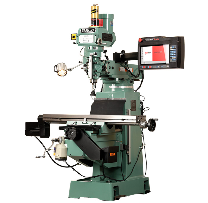
K3 CNC Knee Mills
TRAK Knee Mills offer the flexibility of manual or CNC operation, featuring real handwheels for manual control and the option of ProtoTRAK RMX or KMX CNC systems. These machines are ideal for machinists seeking versatile milling solutions.
-
Table Size:
10″ x 50″
-
T-Slots:
3 x .625″ x 3″
-
Table Travel:
32″
-
Saddle Travel:
16″
-
Knee Travel:
16″
-
Spindle Taper:
R8
-
Spindle Motor HP:
3 HP
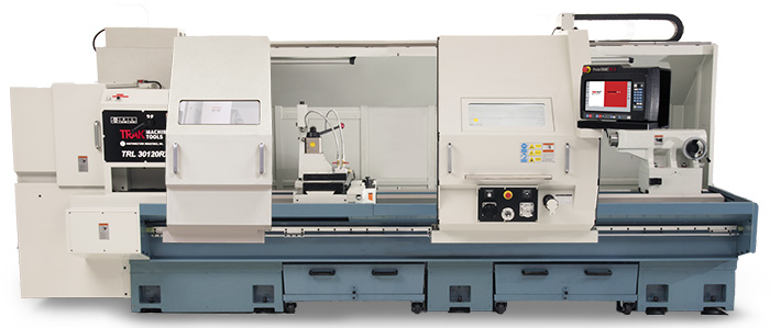
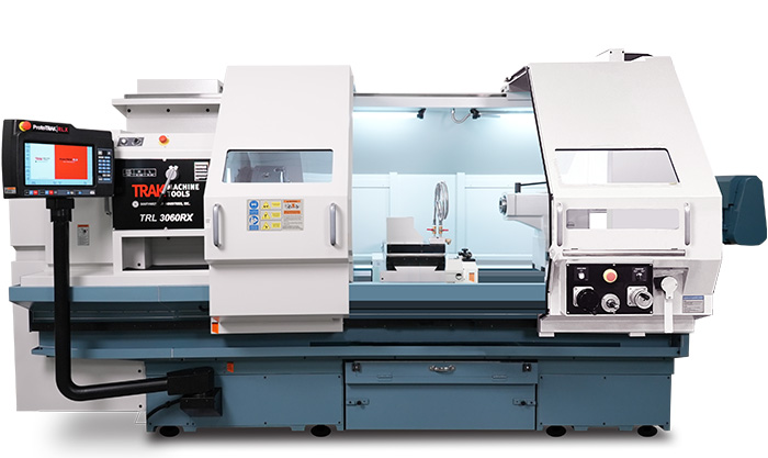
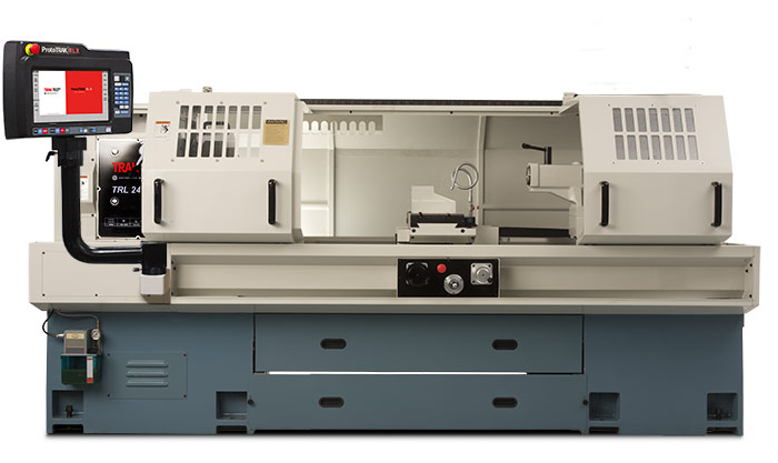
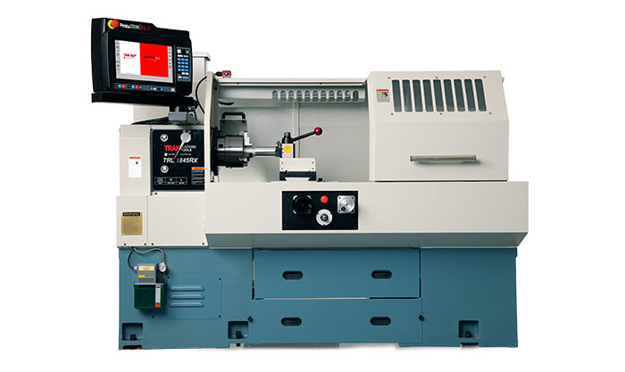
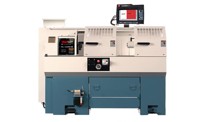
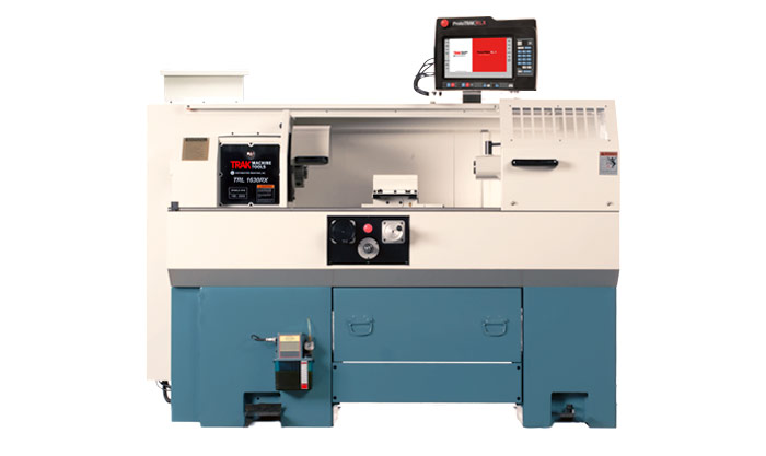
TRLRX Series Lathes
TRAK Toolroom Lathes offer both manual and CNC operations, featuring the ProtoTRAK RLX CNC for user-friendly control. With programmable spindle speeds and optional turrets for automated tool changes, they enhance productivity and flexibility in turning tasks.
-
Swing Over Bed:
33″
-
Distance Between Centers:
118″
-
Spindle Through Hole:
6.30″
-
Spindle Speed Range RPM:
20 - 415, 40 - 1,300
-
Swing Over Bed:
33″
-
Distance Between Centers:
60″
-
Spindle Through Hole:
6.3″
-
Spindle Speed Range RPM:
20 - 415, 40 - 1,300
-
Swing Over Bed:
24″
-
Distance Between Centers:
70″
-
Spindle Through Hole:
4.09″
-
Spindle Speed Range RPM:
40 - 670, 100 - 1,800
-
Swing Over Bed:
18″
-
Distance Between Centers:
45″
-
Spindle Through Hole:
2.36″
-
Spindle Speed Range RPM:
80 - 850, 250 - 2,500
-
Swing Over Bed:
16″
-
Distance Between Centers:
30″
-
Spindle Through Hole:
1.57″
-
Spindle Speed Range RPM:
150 - 4,000
-
Swing Over Bed:
16″
-
Distance Between Centers:
30″
-
Spindle Through Hole:
2.12″
-
Spindle Speed Range RPM:
150 - 2,500
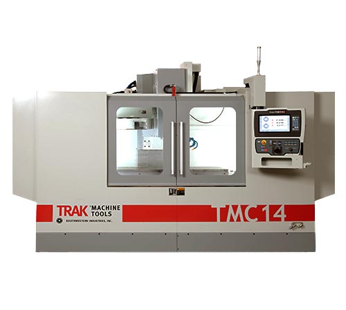
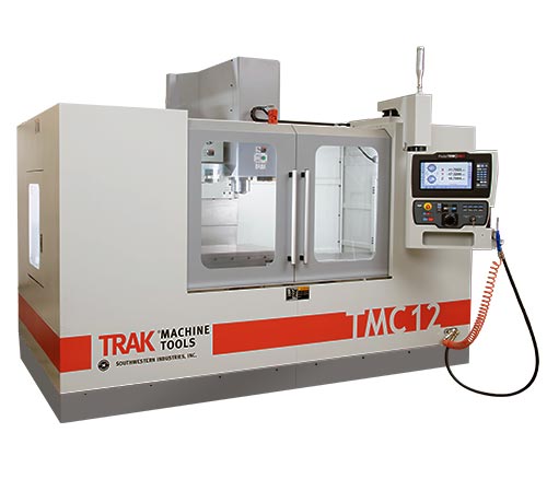
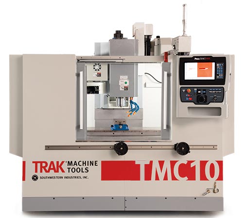
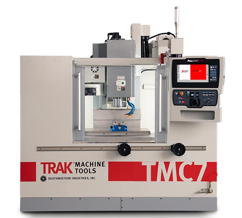
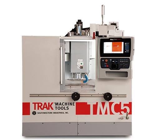
Toolroom Machining Centers
-
Table Size:
62.99″ x 23.62″
-
Travels:
60″ x 27″ x 25″
-
Footprint:
60″ x 27″ x 25″
-
Horsepower:
22.5/15
-
Table Size:
51.18″ x 23.62″
-
Travels:
50″ x 27″ x 25″
-
Footprint:
133.86″ x 144.76″
-
Horsepower:
22.5/15
-
Table Size:
44.09″ x 19.69″
-
Travels:
40.75″ x 20″ x 20″
-
Footprint:
111″ x 135″
-
Horsepower:
15/10
-
Table Size:
35.43″ x 19.69″
-
Travels:
30″ x 20″ x 20″
-
Footprint:
97″ x 135″
-
Horsepower:
15/10
-
Table Size:
27.56″ x 15.75″
-
Travels:
20″ x 16″ x 20″
-
Footprint:
85″ x 129.25″
-
Horsepower:
15/10
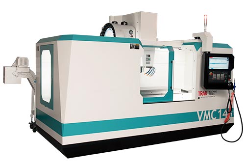
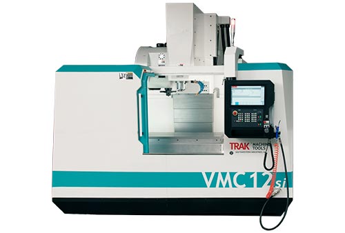
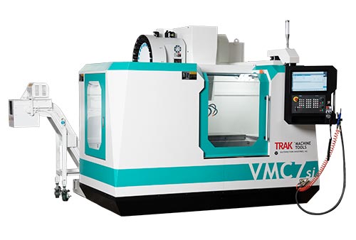
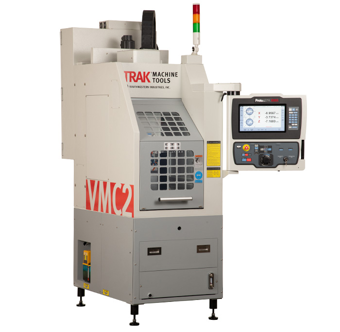
Vertical Machining Centers
TRAK Toolroom Machining Centers, equipped with the ProtoTRAK RMX CNC, offer unmatched flexibility for both manual and CNC operations. Complementing them, the TRAK VMCsi Vertical Machining Centers feature the advanced SINUMERIK ONE CNC, providing high-performance solutions for demanding production environments. Both series deliver precision and efficiency to meet diverse machining needs.
-
Table Size:
62.99″ x 23.62″
-
Travels:
60″ x 27.5″ x 25″
-
Footprint:
180″ x 126.50″
-
Horsepower:
67/26.8
-
Table Size:
51.18″ x 23.62″
-
Travels:
50″ x 27.5″ x 25″
-
Footprint:
168.25″ x 126.50″
-
Horsepower:
67/26.8

-
Table Size:
44.09″ x 19.69″
-
Travels:
40″ x 20″ x 20″
-
Footprint:
144″ x 112″
-
Horsepower:
41.5/20
-
Table Size:
35.43″ x 19.69″
-
Travels:
30″ x 20″ x 20″
-
Footprint:
144″ x 112″
-
Horsepower:
41.5/20
-
Table size:
18″ x 15″
-
Travels:
14″ x 12″ x 17″
-
Footprint:
52″ x 30.5″
-
Horsepower:
4.5/3
Turning Centers
TRAK TCsi Turning Centers are high-precision CNC production lathes featuring the advanced SINUMERIK ONE CNC control. Designed for efficient setups and versatile machining, they offer integrated spindles and robust construction to meet demanding production requirements.
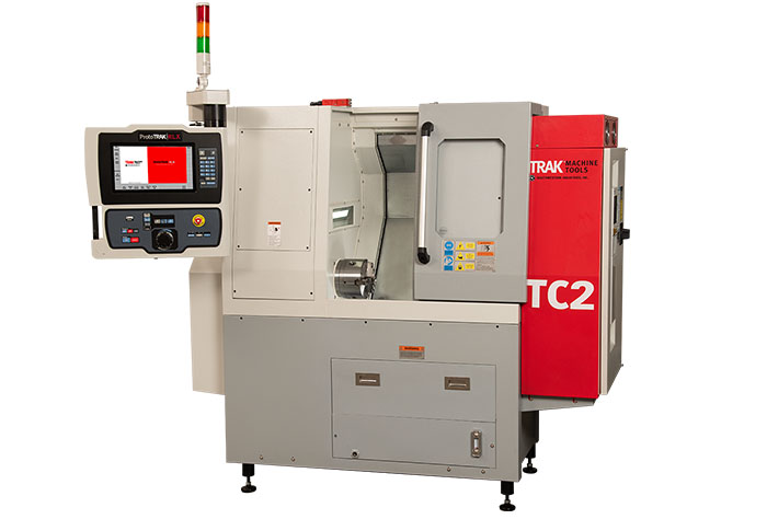
-
Maximum Swing:
12″
-
Maximum Turning Length:
11″
-
Number of Tools:
8 Stations
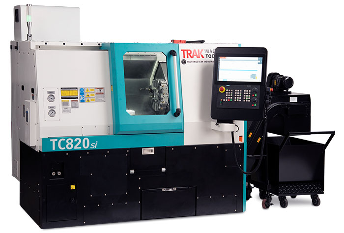
-
Height of Centers:
41.3″
-
Maximum Turned Length:
20″
-
Number of Tools:
12 Stations (Bolt-on)
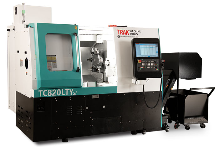
-
Height of Centers:
47.3″
-
Maximum Turned Length:
19.29″
-
Number of Tools:
12 Live Tool Stations (BMT45)
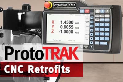
ProtoTRAK CNC Retrofits
TRAK Machine Tools offers ProtoTRAK CNC retrofits to upgrade manual knee-type milling machines, such as Bridgeport models, enhancing productivity with user-friendly controls and advanced features. Options include the ProtoTRAK RMX and KMX CNCs, both available in 2 or 3-axis configurations, designed to improve efficiency in various machining tasks.
ProtoTRAK CNC Upgrades
TRAK Machine Tools offers ProtoTRAK CNC upgrades to enhance the performance of older models like the M2, M3, MX2, MX3, AGE2, and AGE3. Customers can choose between the ProtoTRAK RMX CNC, which provides powerful features for manual milling and enhanced assistance, and the ProtoTRAK KMX CNC, known for its ease of use and improved Auto Geometry Engine®. Both upgrades aim to improve productivity while maintaining a user-friendly interface.